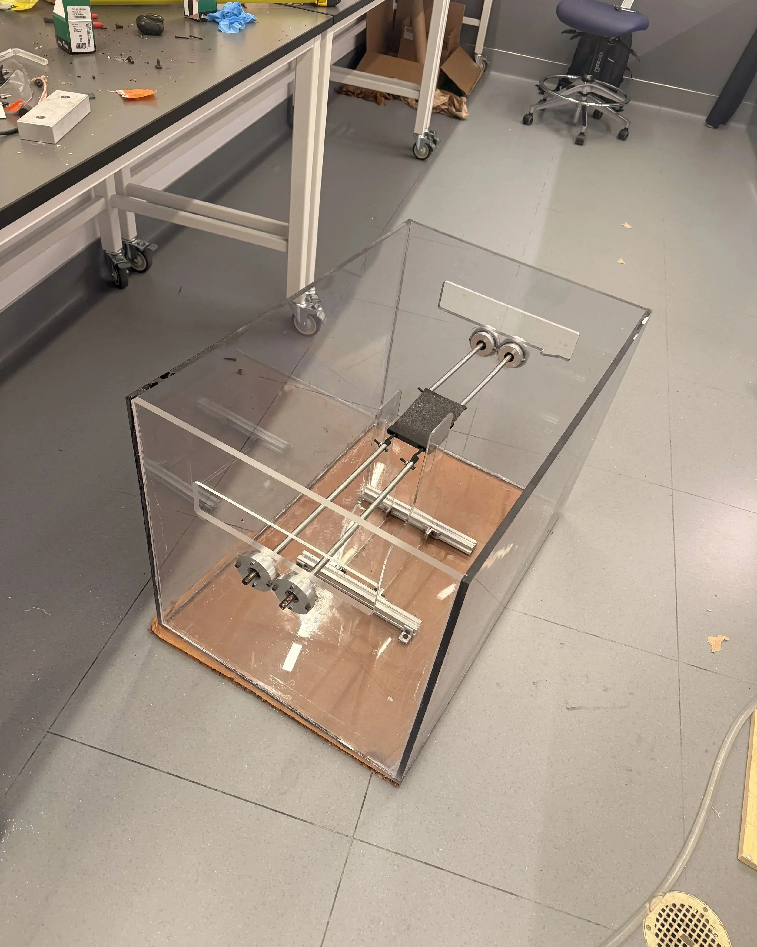
DiBenidetto Lab Tank Test Apparatus
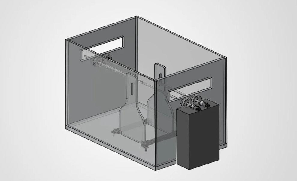
The goal of this project was to design a dedicated test tank that would let the Dibenidetto lab collect data on how an undulating carpet pumps particles across the water surface. The old test apparatus tanks transmitted vibration from the drive motor through the frame and shook the tank, blurring the imaging and adding motion unrelated to the pumping itself, while stray room light washed out the particles we were trying to track. I designed the new apparatus in SolidWorks specifically to remove those error sources by isolating the motor from the tank structure so drive vibration couldn't reach the water, rigidly fixing the camera and undulator relative to one another, and enclosing the tank with controlled backlighting so every run was imaged under identical conditions.
Designing the tank
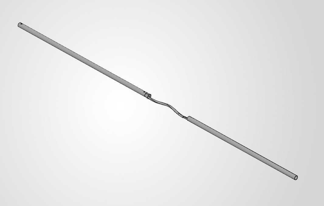
I designed a water tank test apparatus for free-surface undulator experiments. I started by establishing the load path from hydrostatic wall pressure through the frame and drive members. I analyzed the walls as flat plates under hydrostatic loads, making them thick enough to meet a 3× factor of safety, where deflection rather than stress governed. A trade study drove the choice of cast over extruded acrylic to avoid stress cracking at solvent-bonded joints. I sized the drive rods and support members against bending and buckling so they could not deflect enough to disturb the free surface during testing.
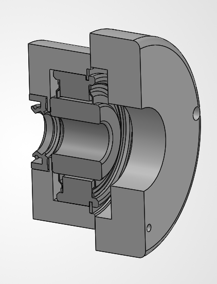
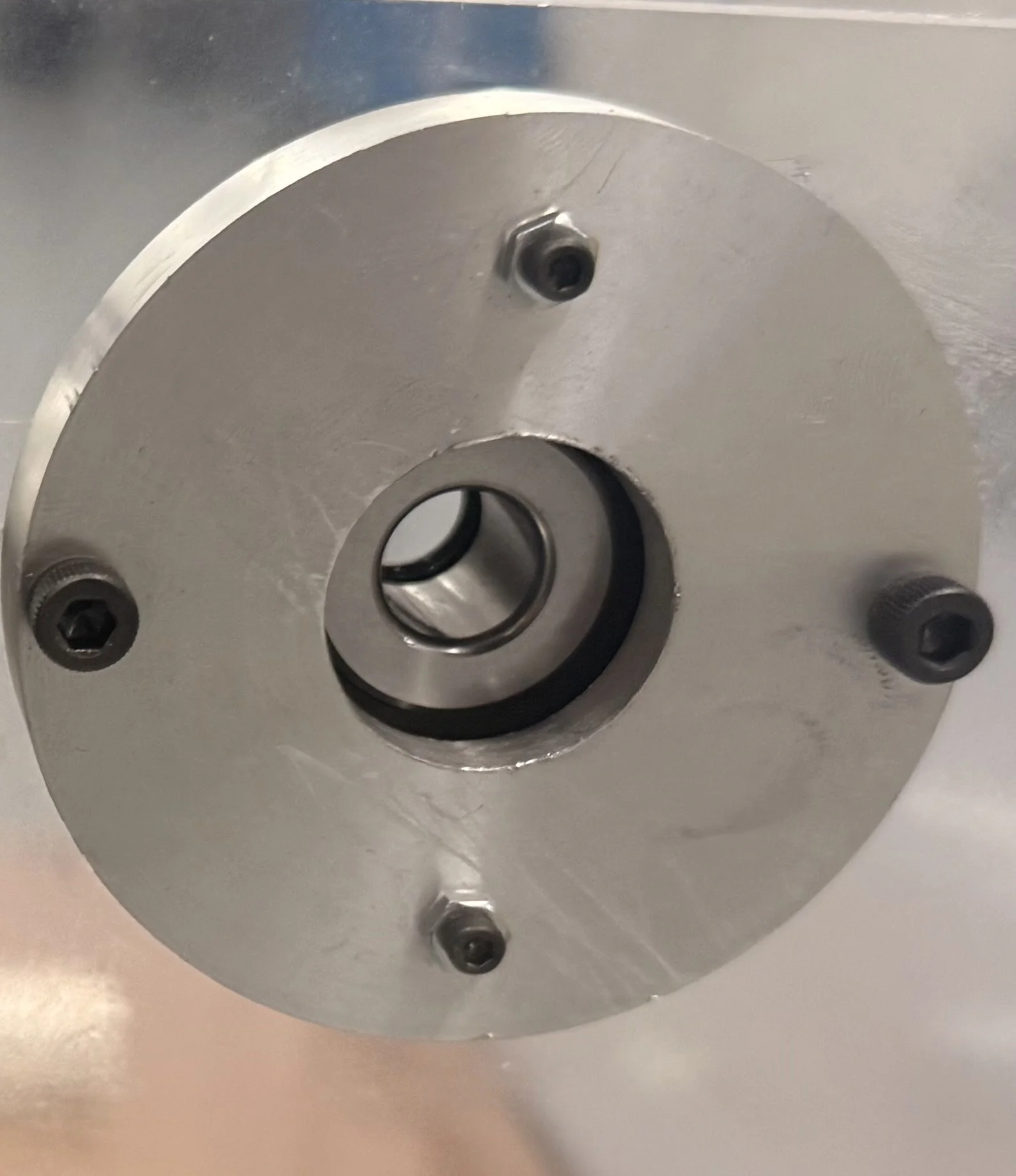
The rotary housing was the most constrained piece, since it had to pass a rotating shaft through a submerged wall while staying rigid, sealed, and serviceable. I designed it as a bored round housing so the bearing bore, seal seat, and outer diameter shared a common axis, minimizing runout and the vibration it would transmit into the water. Rather than radial bolts, which would have broken into the bearing bore at its highest-load section, I specified a threaded end cap sealed with a rotary seal. This kept the housing symmetric, reduced stress, and allowed maintenance access without disassembling the tank.
Building the Tank
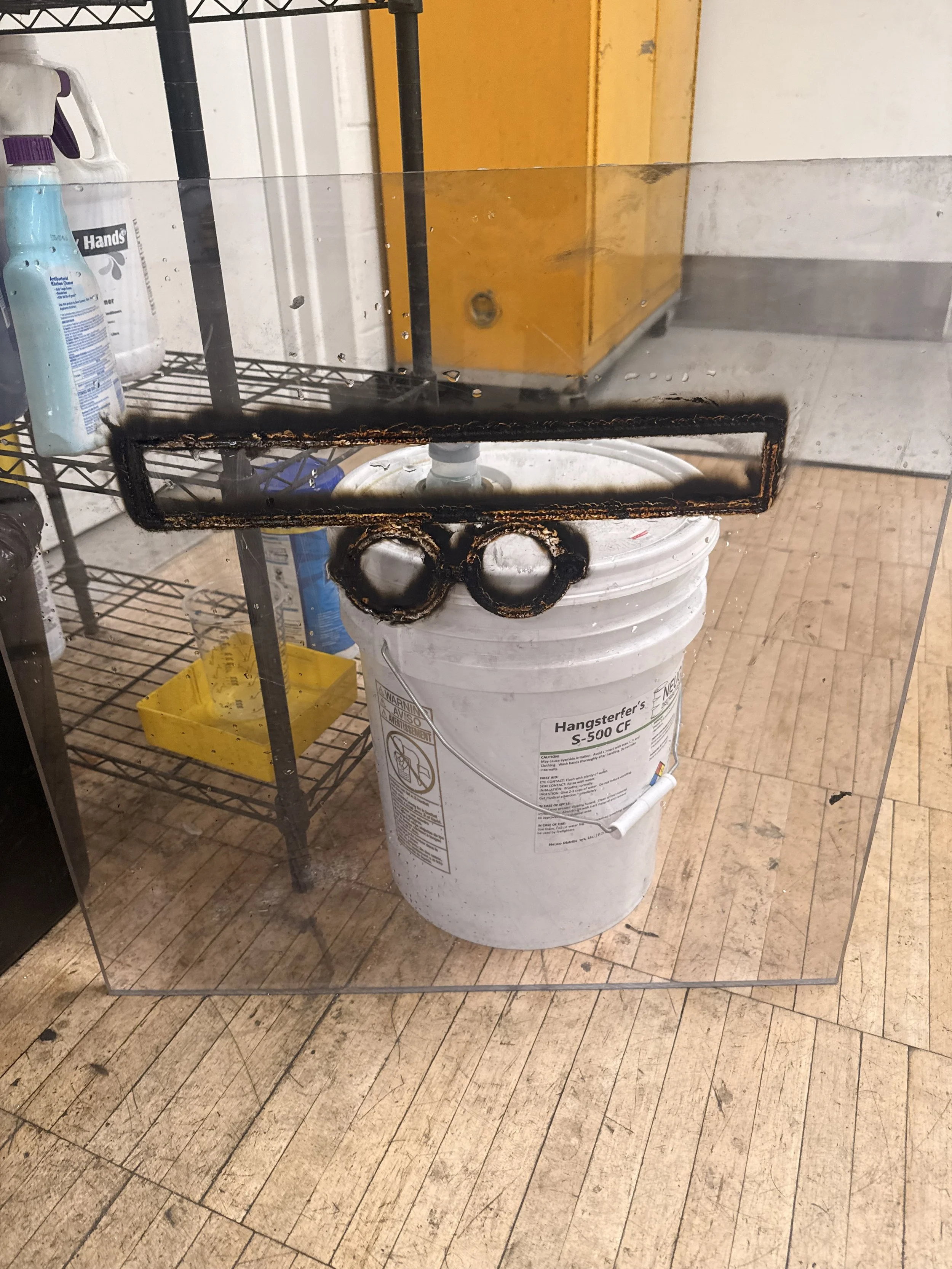
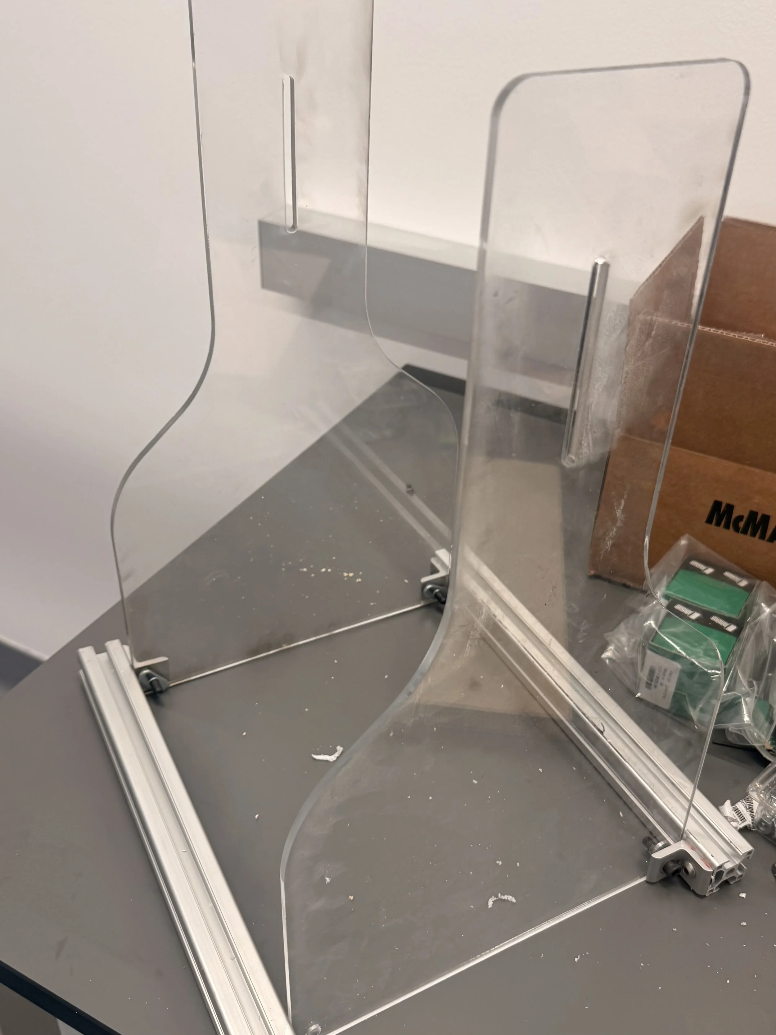
I CNC machined the rotary housing from aluminum stock, cutting the bearing bore, seal seat, and threaded end-cap opening so the critical features stayed concentric. The acrylic panels were originally meant to be laser cut, but the ½ in cast stock burned and left charred, crazed edges that would have been poor surfaces for solvent bonding. So I switched to CNC routing the panels instead, which gave clean, square edges and tight enough tolerances for the joints to weld properly. I then solvent-welded and braced the tank, and installed the housing through the wall penetration with its O-ring seal. The tank functioned as intended and is in use in the Dibenidetto lab to collect data on the undulator.