Thrust Vector Controlled Rocket (in Progress)
The purpose of this project is to design a Thrust Vector controlled rocket that allows for stabilization and accurate positioning of the the rocket.
Designing the Thrust Vectoring
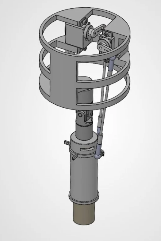
I began by deriving the equations of motion using Lagrangian mechanics to model how actuator force translates into torque about the motor gimbal. I then evaluated the available actuator rods for buckling and shear. Factors of safety were in the hundreds across all candidate rods, showing that strength was not the limiting constraint. This shifted the design focus to stiffness, friction, linkage geometry, and swivel clearance.
I selected 3'' carbon steel rods because they were the shortest available option and provided roughly 2.4× the axial stiffness of a 9'' rod. Steel was preferable to aluminum for the same reason, as switching to aluminum would save negligible weight while substantially reducing stiffness. I attached the rods just below the pivot rather than at the center of mass, because for a parallel rod, the lever arm equals the radial offset from the motor axis. Therefore, moving the attachment point farther down provides essentially no additional torque while requiring a longer rod, reducing axial stiffness because stiffness scales as 1/L. I angled the anchors outboard toward the tube wall rather than running them parallel, which allows a larger lever arm within the available space. Finally, I selected 50° ball joints rather than the more common 22° joints to provide greater angular freedom and reduce the risk of binding throughout the gimbal's range of motion.
Next Steps
My next step is to order parts. I will then build the gimbal assembly and mount it in a section of the body tube, wiring it up with the servos, controller, and battery so I can verify the electronics work. I will then begin to test the accuracy of the gimbal system with a set of live fire tests.