NACA Wing Project
The goal of this project was to design, build, and destructively test a lightweight aluminum wing that could carry a 97 lbf load at its tip without failing while minimizing weight. The design was evaluated based on its ability to withstand the required load, minimize weight, and limit tip deflection. Our final wing weighed 1 lb 10.8 oz, held the required 97 lbf with only minor skin rippling, and ultimately failed at roughly 260 lbf, holding 2.7 times the required load, with a strength-to-weight ratio of about 148.
The Design
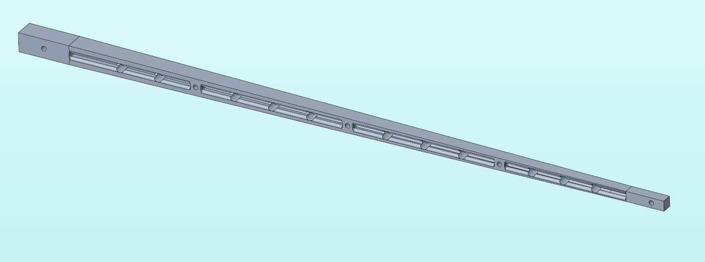
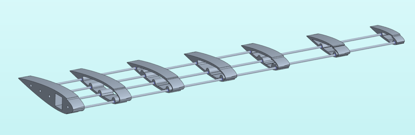
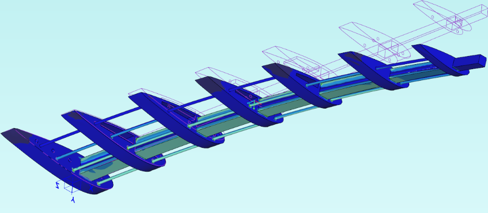
I began the wing design from first principles, modeling it as a cantilever beam and using hand calculations to determine the minimum spar moment of inertia required to support the 97 lbf tip load with a 1.5 safety factor. I compared three spar cross-sections: a single I-beam, double C-beam, and double L-beam. I selected the tapered single I-beam for its bending stiffness per unit weight, then narrowed five candidate geometries down to the lightest one that satisfied the required stiffness. Next, I modeled the full wing assembly in PTC Creo and performed static and buckling finite element analyses (FEA) under the 97 lbf tip load with the root bulkhead fixed. The simulations confirmed the hand calculations and, more importantly, revealed that skin buckling would govern failure, which redirected the rest of the design. I iterated the model against those results: tightening bulkhead spacing near the root where bending stress was highest, adding stringers along the lower compression surface to shorten the unsupported skin panels, and adding a small taper at the web-flange junction to relieve a stress concentration Creo flagged at the re-entrant corner. Finally, I incorporated a linear spanwise taper and lightening holes to remove material from the outboard sections, where the bending moment approaches zero, cutting an additional 6.2% of the weight while holding the safety factor.

Building the wing
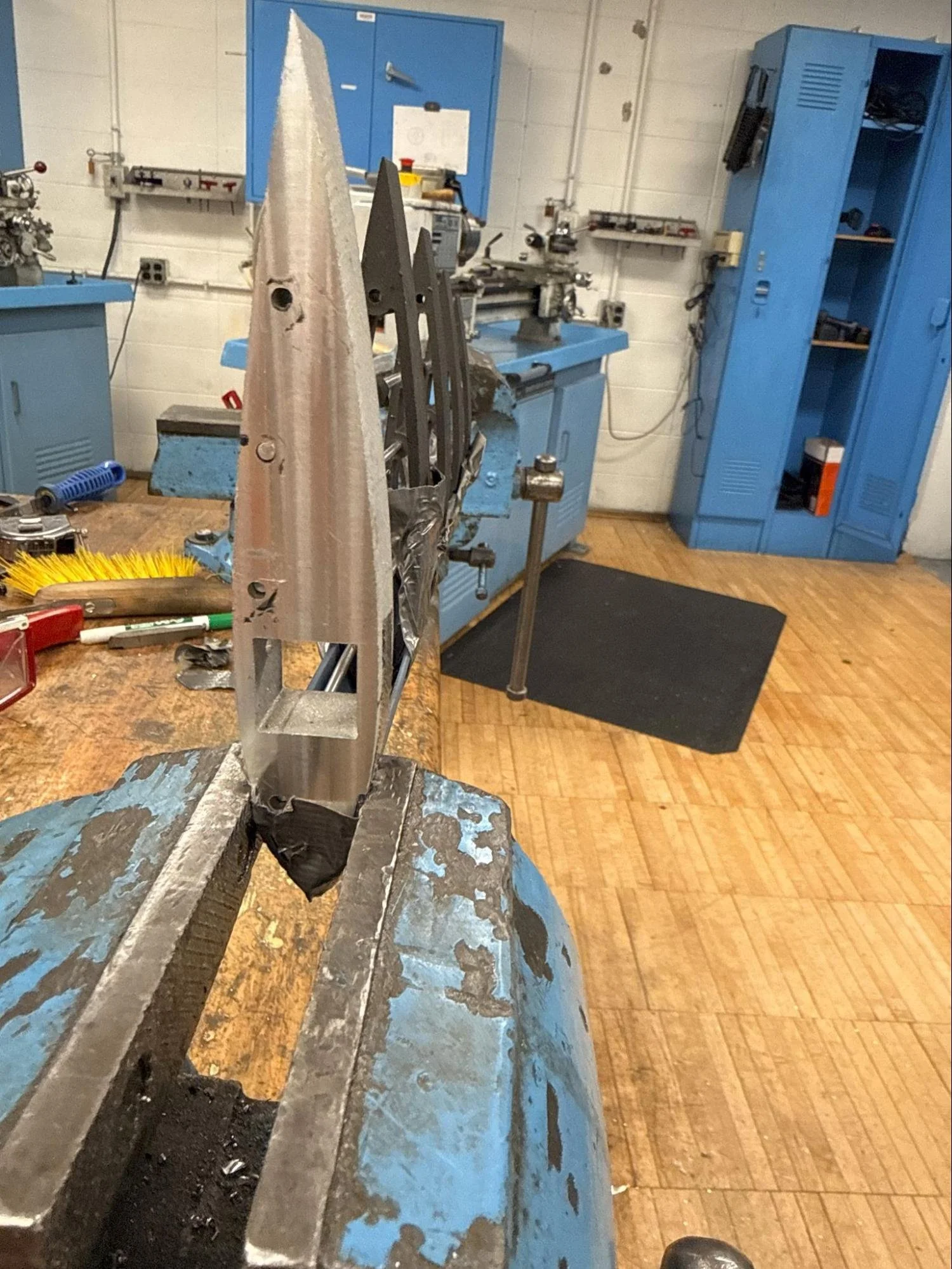
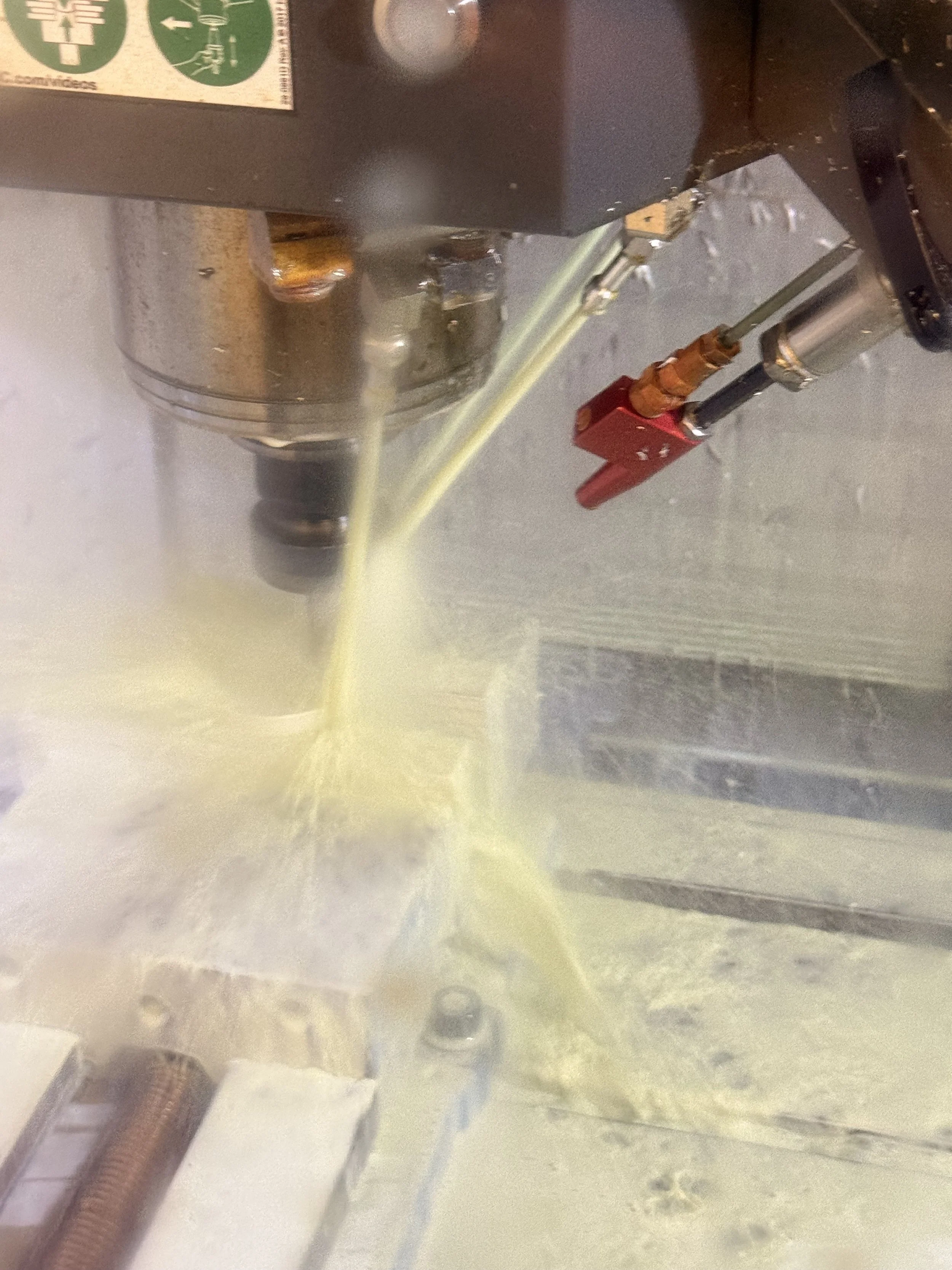
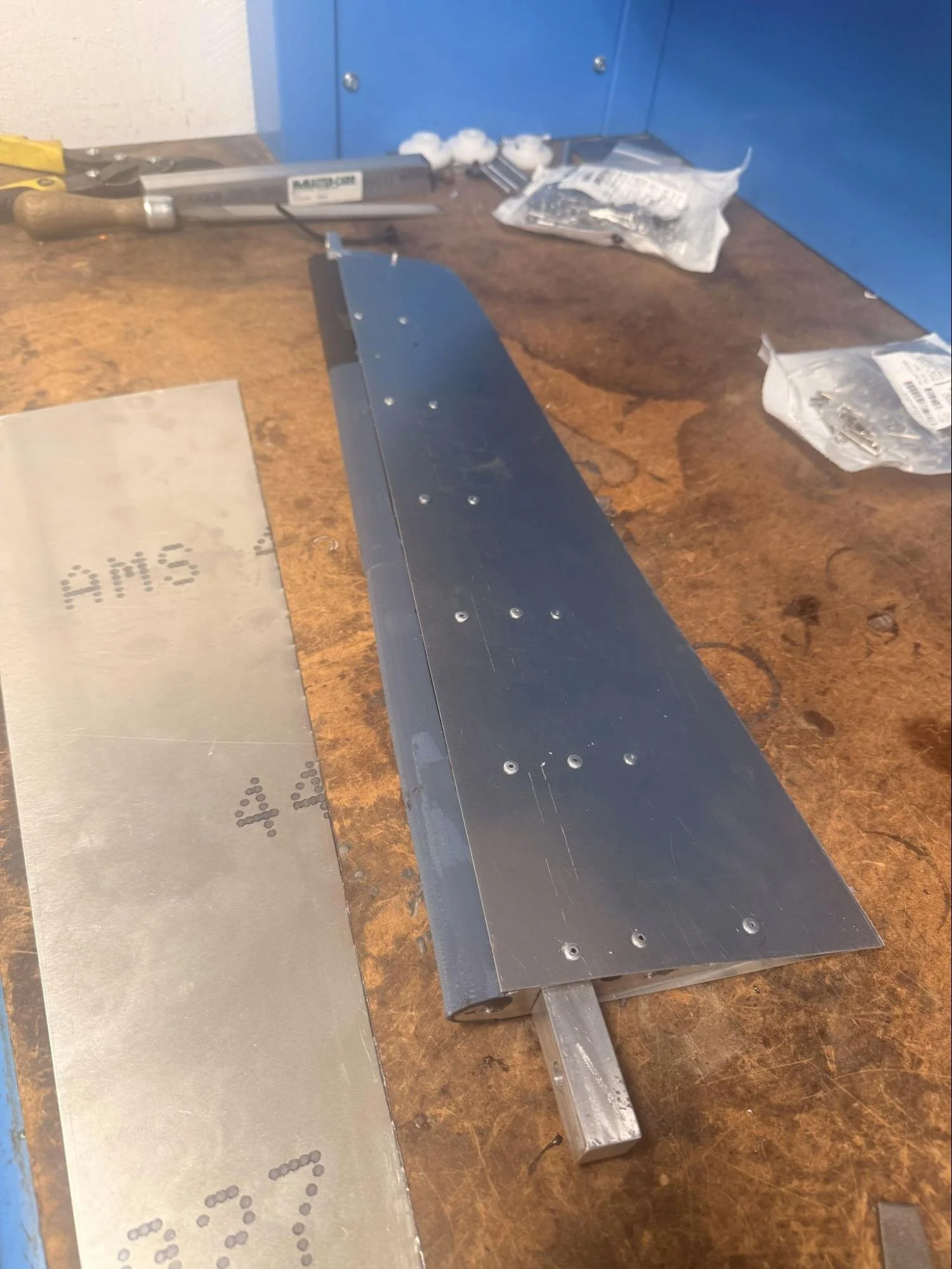
I machined the tapered I-beam spar from 7075-T6 aluminum on a Haas 3-axis CNC mill in two operations, profiling the top flange and lightening holes first, then flipping and shimming the workpiece on aluminum spacers to keep the central axis parallel to the bed before profiling the bottom flange and tip taper. I waterjet-cut the root and tip bulkheads from 6061 stock and hand-tapped the 10-32 mounting holes, while SLS 3D-printing the five interior ribs in PA12 nylon. I then cut and hand-formed the 0.016-inch and 0.025-inch 6061-T6 skins with aviation snips, then riveted the skins, stringers, and ribs to the spar using aluminum blind rivets at roughly 1 in spacing, matching rivet grip length to each local stack-up.
Testing the wing
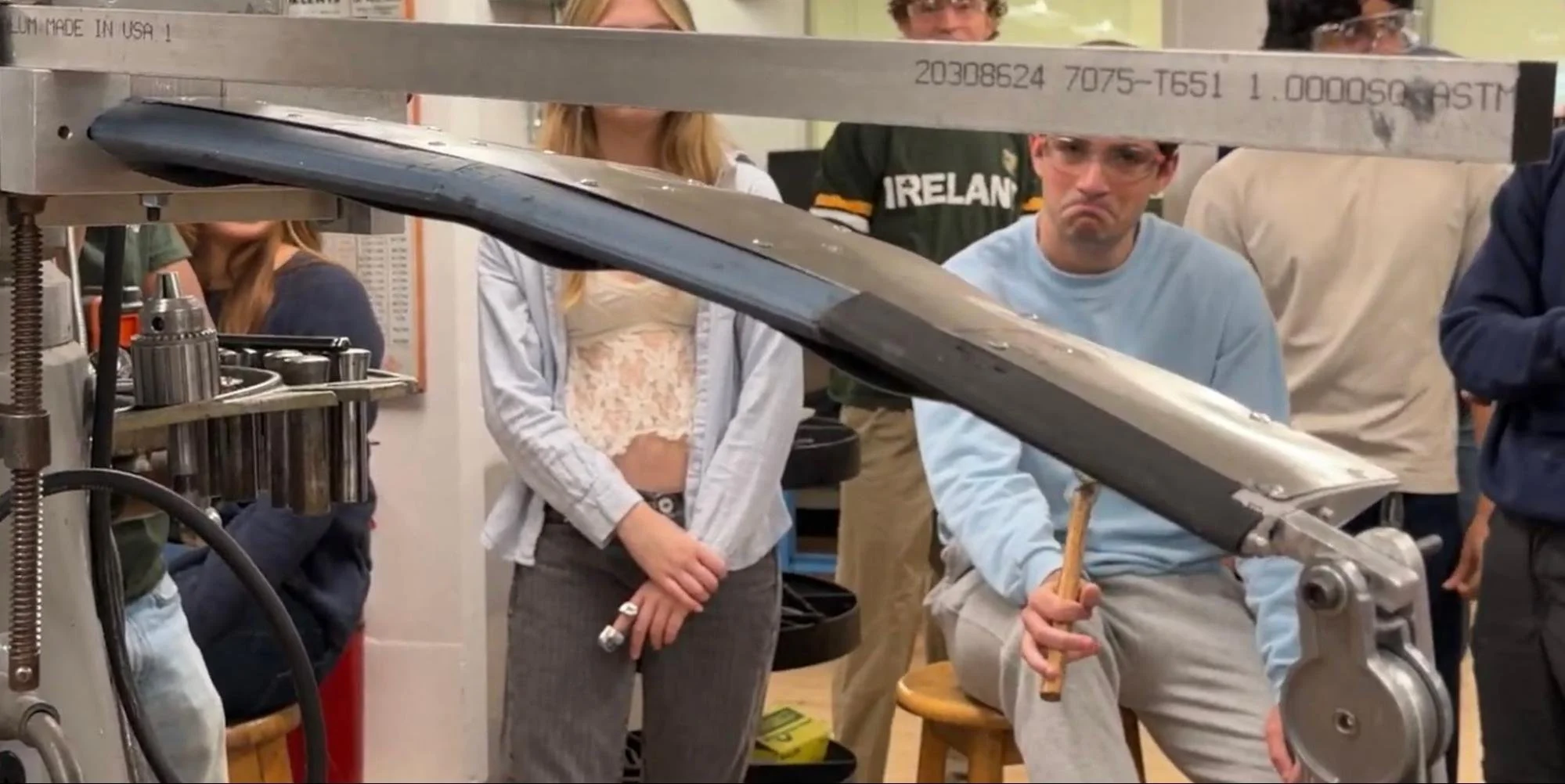
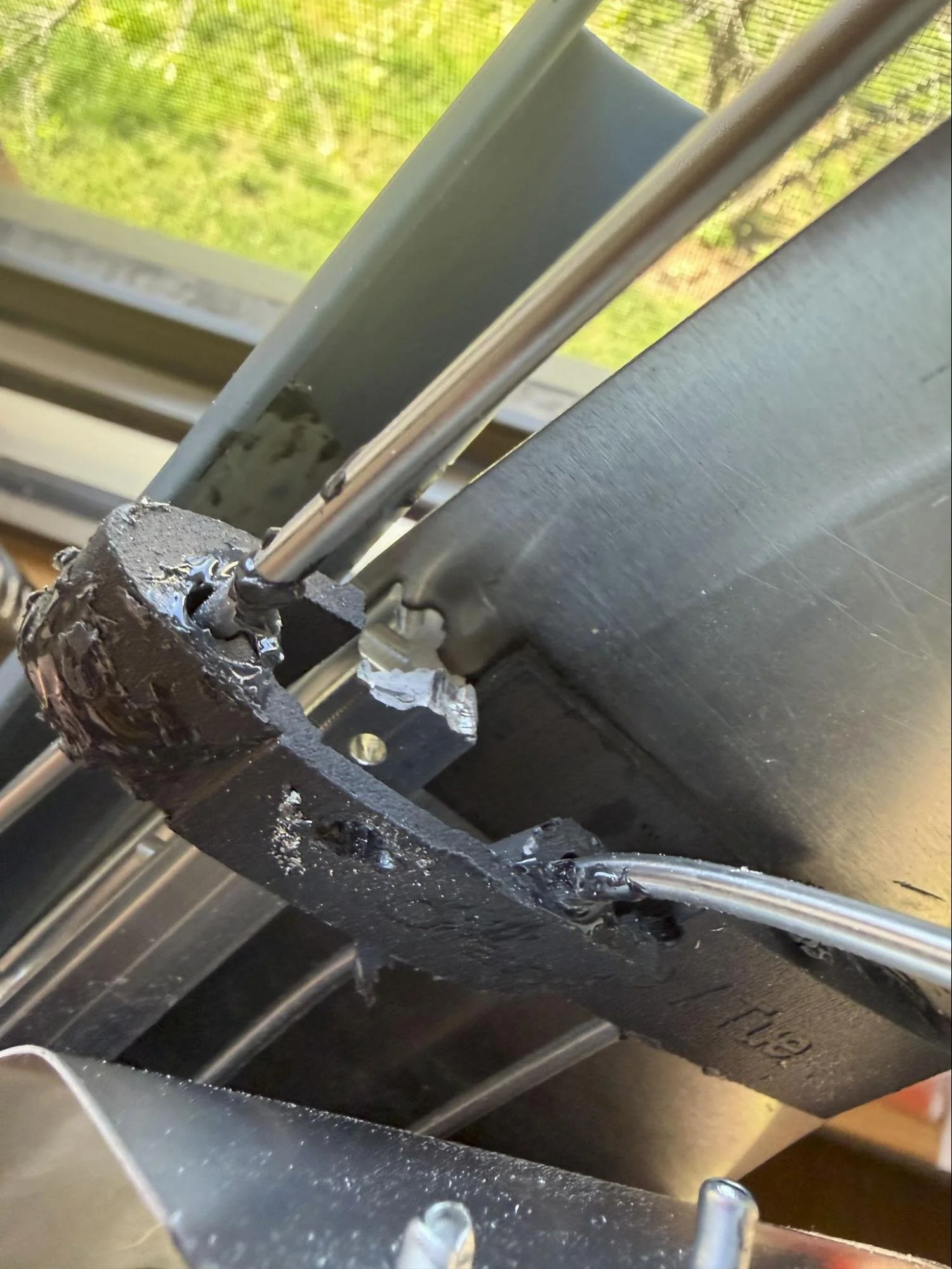
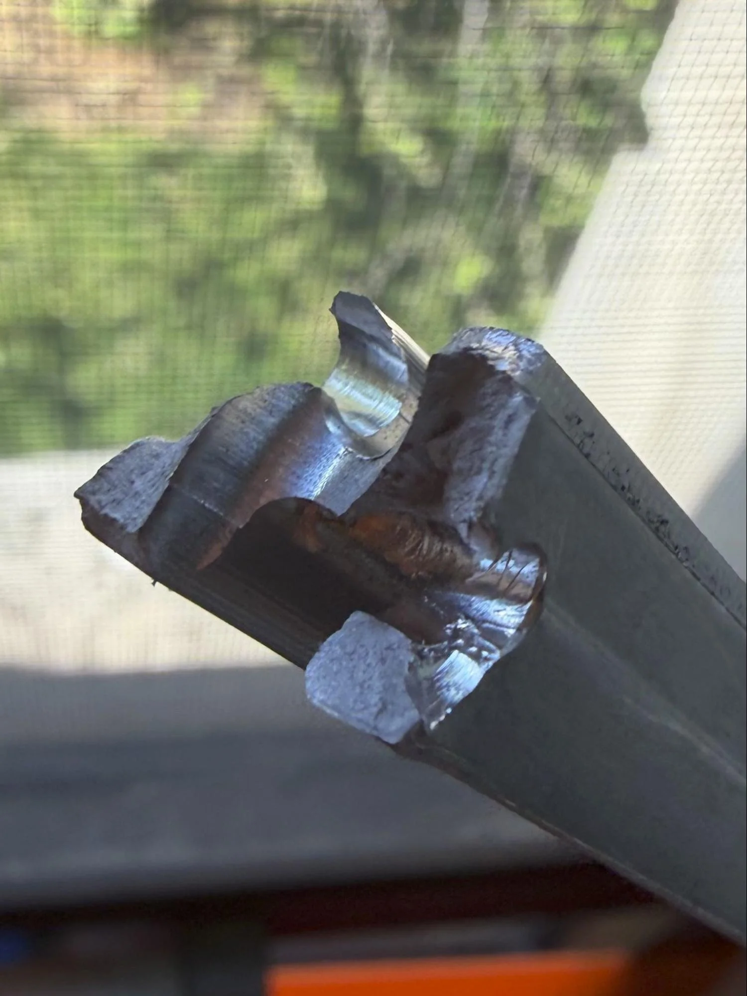
The finished wing weighed 1 lb 10.8 oz and supported the required 97 lbf tip load with only minor skin rippling, consistent with the FEA prediction that local skin buckling would be the first visible response at the design load. The wing continued to carry substantially higher loads, ultimately failing at approximately 260 lbf, 2.7 times the design requirement, with a strength-to-weight ratio of approximately 148. The failure itself came down to a manufacturing mistake. During assembly, a rivet had been driven through the web of the I-beam instead of the flange. The web carries the shear load along the entire span and has no redundant load path, so the stress concentration at that hole, combined with the already-thinned cross-section from the spanwise taper, caused the early failure.